

Product Overview
WENC2 is a wireless transmitter-receiver system that carries motor encoder signals in industrial environments. The TX (transmitter) reads encoder inputs on the rotating side, and the RX (receiver) reproduces an identical quadrature signal for the drive — without any software or configuration change on the drive side.
It replaces the encoder cable in applications where pulling cable is difficult or impossible: rotating bobbins, rotary tables, slip-ring systems, multi-axis machines, crane drums, and more.

TX Transmitter Module
Mounted on the motor side, reads encoder signals

RX Receiver Module
Mounted at the drive cabinet, outputs quadrature A/B
How It Works
Read → transmit → reproduce — transparent to your drive
1. Encoder Reading (TX)
The TX module reads the encoder A/B signals on the motor side through opto-isolated inputs.
2. Wireless Transmission
Data is sent point-to-point on the 5 GHz band with CCMP encryption and automatic channel switching.
3. Signal Reproduction (RX)
The RX reproduces an identical HTL quadrature A/B signal for the drive. The drive sees a real encoder; no software or setting change is needed on the drive side.
Key Features
Output Modes (Position Following)
Selected per encoder channel to suit the application
The output the RX gives to the drive is selected separately for each encoder channel in the Output Mode section of the service interface. In the position modes (1–3) no pulse is ever lost: after a short link interruption, the missing pulses are completed as soon as the link returns. In speed mode, the last speed is held during short gaps.
| Mode | Lost-pulse recovery | Delay | On dropout | Best for |
|---|---|---|---|---|
| 0 — Speed transfer (default) | No | Up to the speed filter | Output stops, difference remains | Constant high speed, speed feedback |
| 1 — Position, safe | Yes (rate-limited) | Slightly behind | Falls behind, then catches up | Length measurement, counting |
| 2 — Position, predictive | Yes (rate-limited) | Next to none | Falls behind, then catches up | Low speed, ramps, position tracking |
| 3 — Position, servo | Yes | Next to none | Catches up, slight overshoot and return | Tight position matching; drive position follower (electronic gearing / master-slave) |
Recommendation: speed feedback to the drive → mode 0 · drive position follower → mode 3 · length measurement and counting where no pulse may be lost → mode 1 (choose mode 3 only if a backward step is acceptable).
Model Options
Three variants, same wireless infrastructure
WENC2-S
Single Encoder (MONO)
- 1 encoder channel (A/B)
- 5 GHz wireless communication
- TX: 1x 8-pin terminal
- RX: 1x 8-pin terminal
- Web interface
- 2nd encoder channel
- 3rd encoder channel
WENC2-D
Dual Encoder (DUO)
- 2 encoder channels (A/B)
- 5 GHz wireless communication
- TX: 1x 8-pin terminal
- RX: 1x 8-pin terminal
- Web interface
- 3rd encoder channel
WENC2-T
Triple Encoder (TRI)
- 3 encoder channels (A/B)
- 5 GHz wireless communication
- TX: 2x 8-pin terminal
- RX: 2x 8-pin terminal
- Web interface
Technical Specifications
5 GHz Multi-Channel
Wireless transmission on the 5 GHz band only, with automatic channel switching; unaffected by 2.4 GHz interference
5 GHz3 Encoder Channels
Independent A/B phase inputs, 0–102 kHz per channel
3x A/BEncoder Supply Output
Filtered +23.5 V encoder supply on the TX side, 500 mA continuous
TX OutputWide Supply Range
Reverse polarity, overvoltage (varistor + fuse) and ESD protection
15–30 V DCWeb Interface
Monitoring, diagnostics, pairing and updates from a tablet or phone in service mode
TX + RXParameters Table
| Parameter | TX (Transmitter) | RX (Receiver) |
|---|---|---|
| Wireless Communication | ||
| Wireless standard | Wi-Fi 6 (IEEE 802.11ax), 5 GHz only; 5 GHz robust protocol compliant with Wi-Fi 6ax licensing | Wi-Fi 6 (IEEE 802.11ax), 5 GHz only; 5 GHz robust protocol compliant with Wi-Fi 6ax licensing |
| Topology | Point-to-point, automatic channel switching | Point-to-point, automatic channel switching |
| Link security | Paired MAC verification + CCMP encryption | Paired MAC verification + CCMP encryption |
| RF output power | ≤ 17 dBm | ≤ 17 dBm |
| Antenna | External, 5 GHz, 1.1 dBi | External, 5 GHz, 1.1 dBi |
| Range (line of sight) | > 100 m in open areas; actual range depends on the environment | |
| Input / Output | ||
| Encoder | Input: up to 3 channels A, /A, B, /B (HTL, opto-isolated) | Output: up to 3 channels A, /A, B, /B (HTL push-pull) |
| Connection type | 4-wire (differential) or 2-wire (single-ended) | Directly to the drive's encoder input |
| Pulse frequency | 0–102 kHz per channel (theoretical limit ≈ 150 kHz) | |
| Index (Z) signal | Not used (only A/B is transmitted) | |
| Output current | — | 100 mA sink / 100 mA source per channel; PTC protected, self-recovering |
| Electrical | ||
| Supply voltage | 15–30 V DC (nominal 24 V) | 15–30 V DC (nominal 24 V) |
| Absolute max (short-duration peak) | 42 V | 35 V |
| Typical current @ 24 V | 28 mA (excluding encoder current) | 50 mA (no load) |
| Encoder supply output (terminal 3) | Supply − 0.5 V (+23.5 V at 24 V), 500 mA continuous | — |
| Output level | — | Tracks the supply: ≈ supply − 1 V |
| Input thresholds | LOW < 13.8 V · HIGH > 14.0 V | — |
| Reverse polarity protection | Down to −32 V | Down to −32 V |
| Overvoltage protection | 35 V varistor + fuse | 35 V varistor + fuse |
| ESD rating (terminals) | ±4 kV contact / ±8 kV air | ±4 kV contact / ±8 kV air |
| Timing | ||
| Start-up time | Paired device ≈ 12 s (power → normal operation) · unpaired device ≈ 5 s (power → service mode) | |
| Physical & Environmental | ||
| Enclosure (W × D × H, excl. antenna) | 70 × 103 × 60 mm | 70 × 103 × 60 mm |
| Weight (incl. antenna, excl. terminals) | 120 g | 120 g |
| Mounting | TS35 DIN rail clip + screw holes | TS35 DIN rail clip + screw holes |
| Protection class | IP20 (closed enclosure on request) | IP20 (closed enclosure on request) |
| Operating temperature | −20 °C … +70 °C | −20 °C … +70 °C |
| Storage temperature | −40 °C … +85 °C | −40 °C … +85 °C |
| Relative humidity | 10 – 95 % (non-condensing) | 10 – 95 % (non-condensing) |
| Operating altitude | ≤ 2000 m | ≤ 2000 m |
| Terminals | 2 × 8-pin pluggable screw terminals, 3.81 mm pitch | 2 × 8-pin pluggable screw terminals, 3.81 mm pitch |
| Conductor size | 0.22–0.75 mm² (AWG 24–18) | 0.22–0.75 mm² (AWG 24–18) |

PPR / RPM Coverage
Transparent forwarding — the speed limit depends on encoder PPR
WENC2 is transparent to the drive — it forwards encoder pulses unchanged. The operating pulse frequency range is 0–102 kHz per channel, with a theoretical limit of ≈ 150 kHz. Reference: 6000 RPM @ 1024 ppr (= 102.4 kHz). The speed limit is inversely proportional to PPR: RPM = f × 60 / PPR.
| Encoder PPR | Operating limit | Theoretical limit |
|---|---|---|
| 512 | 12000 RPM | 17500 RPM |
| 1024 | 6000 RPM | 8800 RPM |
| 2048 | 3000 RPM | 4400 RPM |
| 4096 | 1500 RPM | 2200 RPM |
The mechanical limits of the encoder and motor also apply. When the encoder changes, only the PPR parameter in the drive is updated; no setting is required on WENC2.
Terminal Assignments
Continuous terminal numbering 1–16 on all models
TX (Transmitter — Motor Side)
| Terminal | Function | Model |
|---|---|---|
| 1 | +24 V supply input | All |
| 2 | GND | All |
| 3 | +23.5 V encoder supply output | All |
| 4 | GND (encoder) | All |
| 5 | ENC0.A | All |
| 6 | ENC0./A | All |
| 7 | ENC0.B | All |
| 8 | ENC0./B | All |
| 9 | ENC1.A | D, T |
| 10 | ENC1./A | D, T |
| 11 | ENC1.B | D, T |
| 12 | ENC1./B | D, T |
| 13 | ENC2.A | T |
| 14 | ENC2./A | T |
| 15 | ENC2.B | T |
| 16 | ENC2./B | T |
RX (Receiver — Drive Side)
| Terminal | Function | Model |
|---|---|---|
| 1 | +24 V supply input | All |
| 2 | GND | All |
| 3 | GND | — |
| 4 | ENC0.A | All |
| 5 | ENC0./A | All |
| 6 | ENC0.B | All |
| 7 | ENC0./B | All |
| 8 | GND | — |
| 9 | ENC1.A | D, T |
| 10 | ENC1./A | D, T |
| 11 | ENC1.B | D, T |
| 12 | ENC1./B | D, T |
| 13 | ENC2.A | T |
| 14 | ENC2./A | T |
| 15 | ENC2.B | T |
| 16 | ENC2./B | T |
Note — 2-wire encoder: only A and B are connected. On the TX side, the /A and /B terminals are bridged to GND; no bridging is done on the RX side. RX outputs are HTL level (24 V) and connect directly to the drive's encoder input.
Connection Diagrams
Wiring for all three models
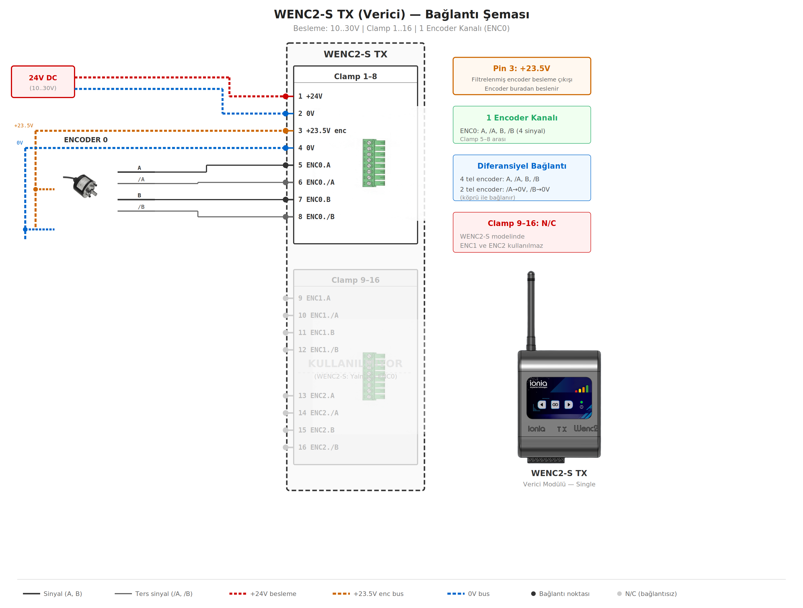
WENC2-S TX
Single encoder, transmitter side
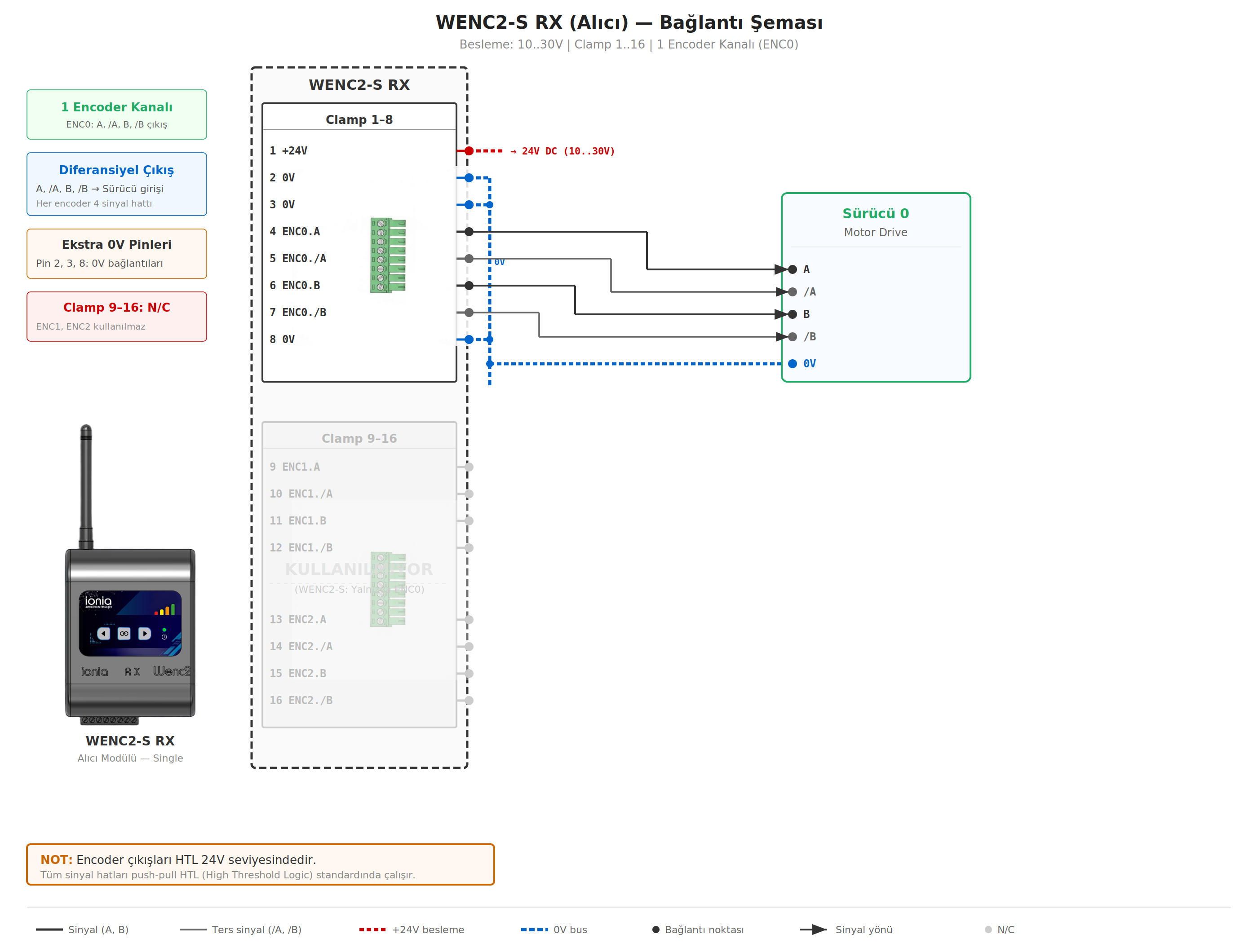
WENC2-S RX
Single encoder, drive side
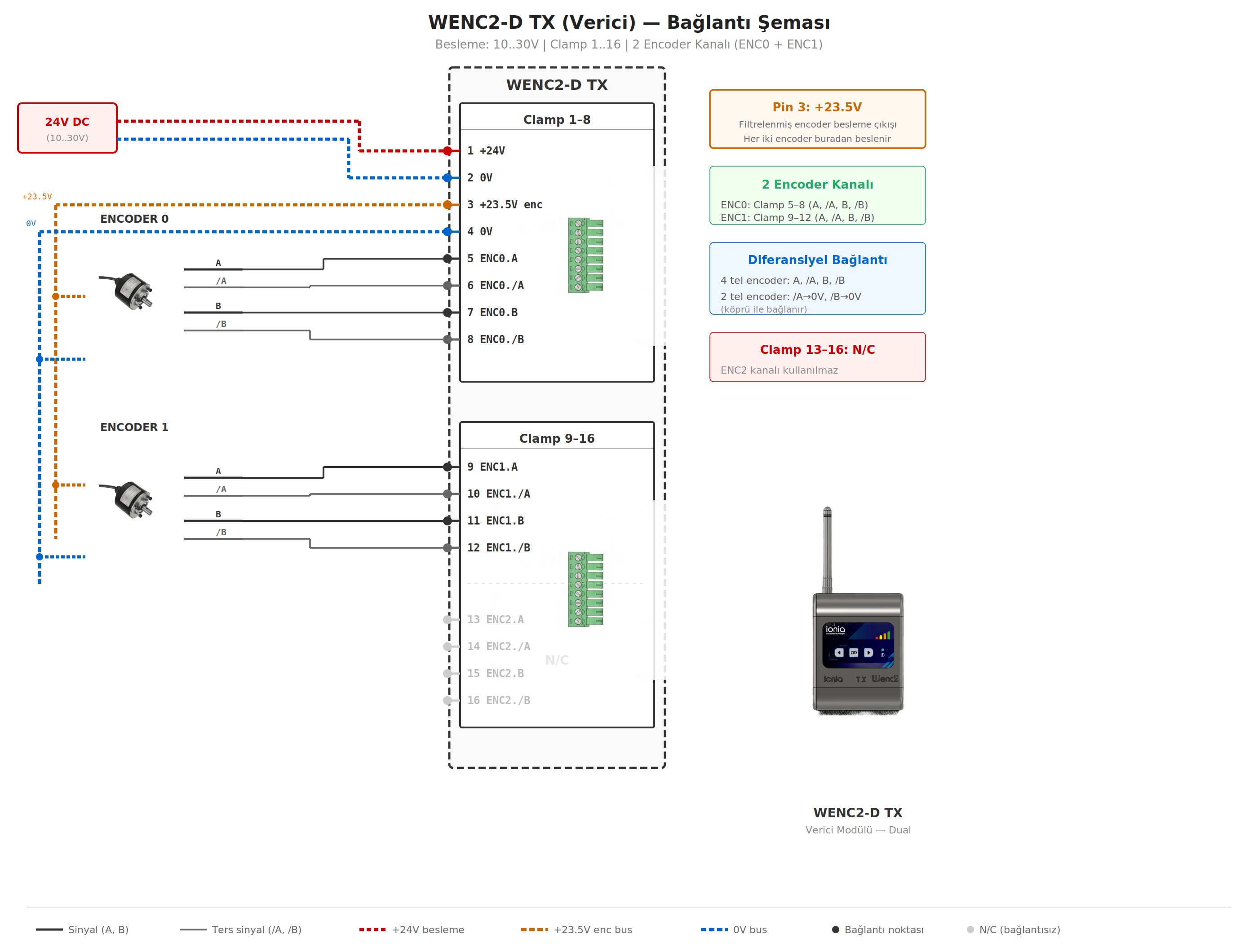
WENC2-D TX
Dual encoder, transmitter side
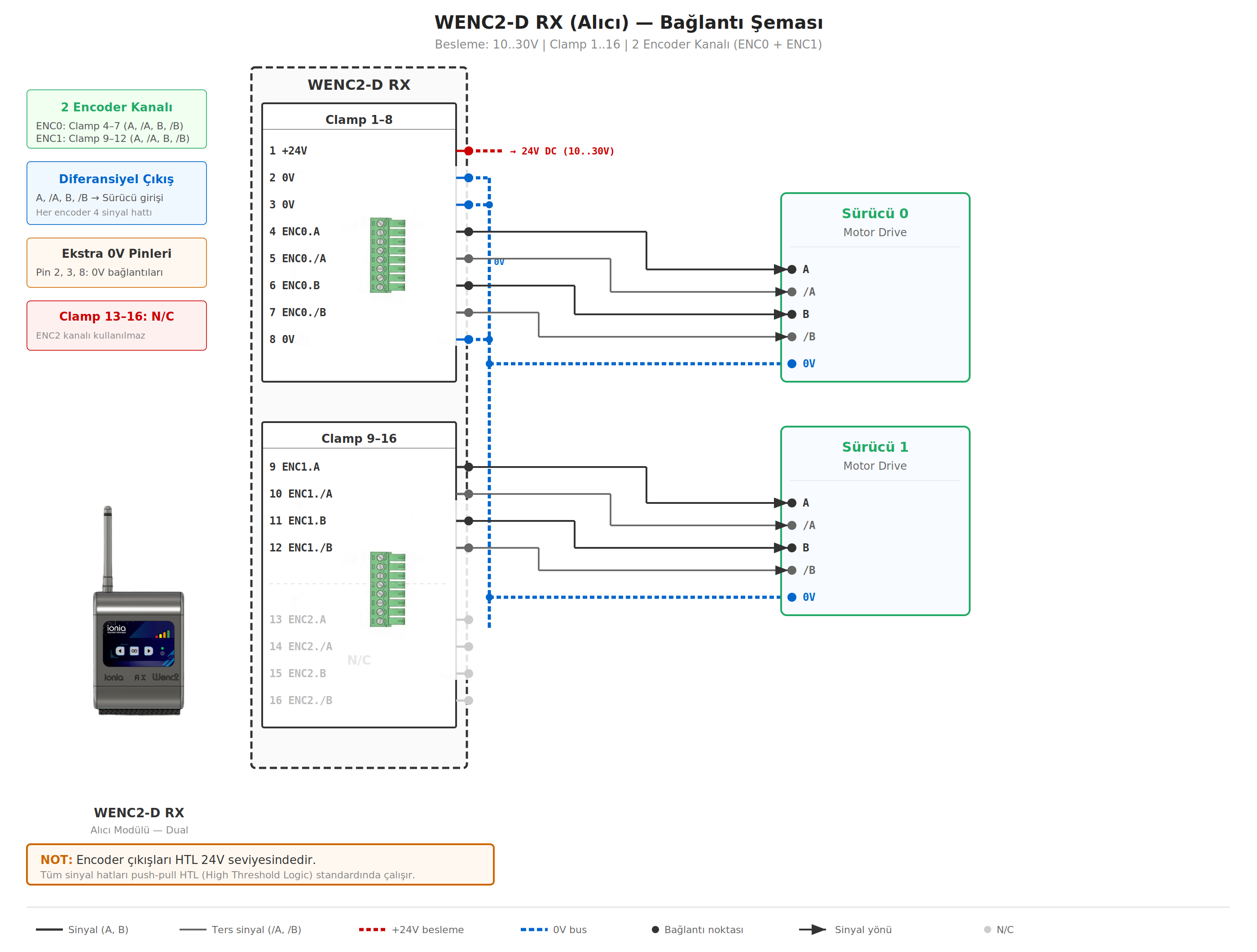
WENC2-D RX
Dual encoder, drive side
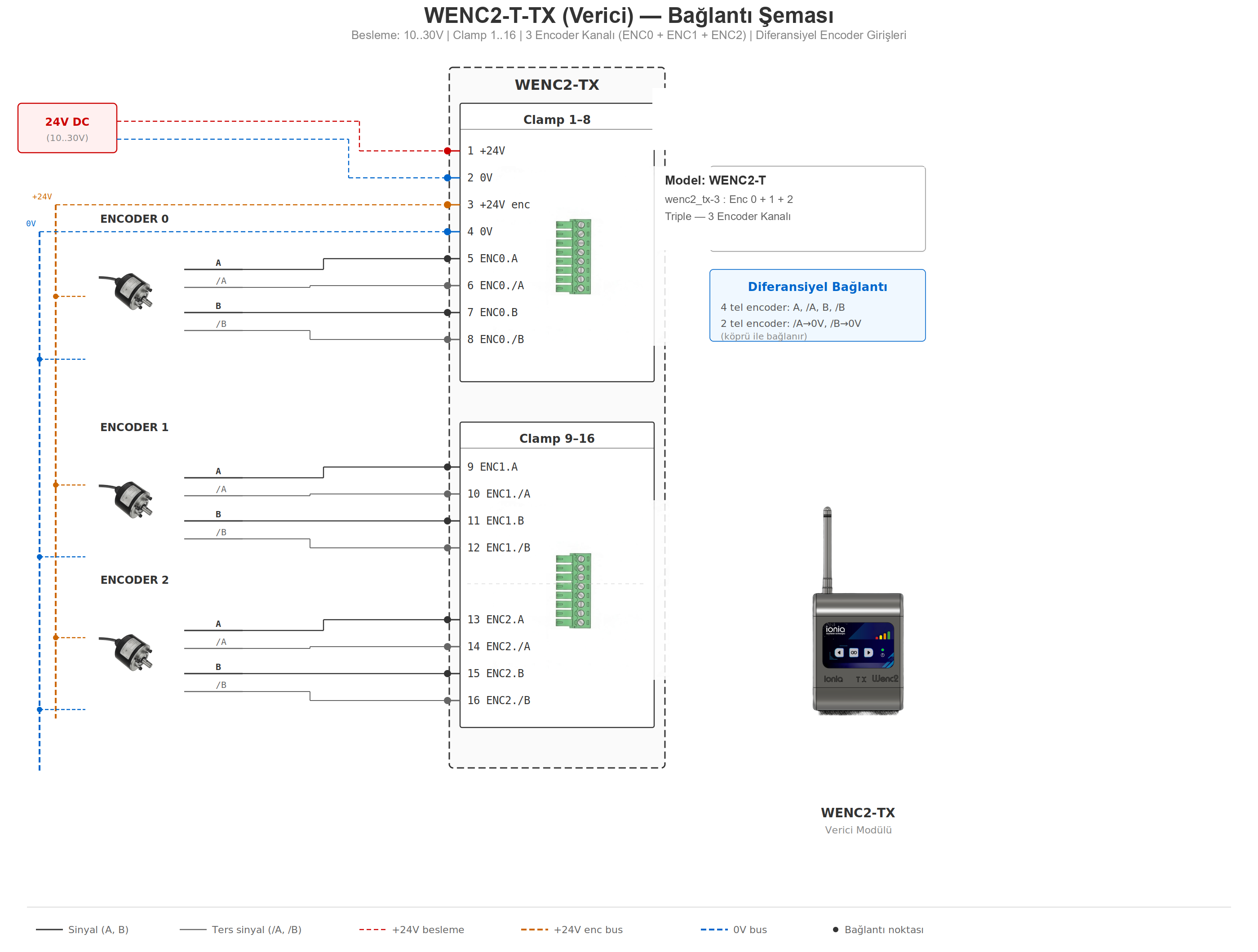
WENC2-T TX
Triple encoder, transmitter side
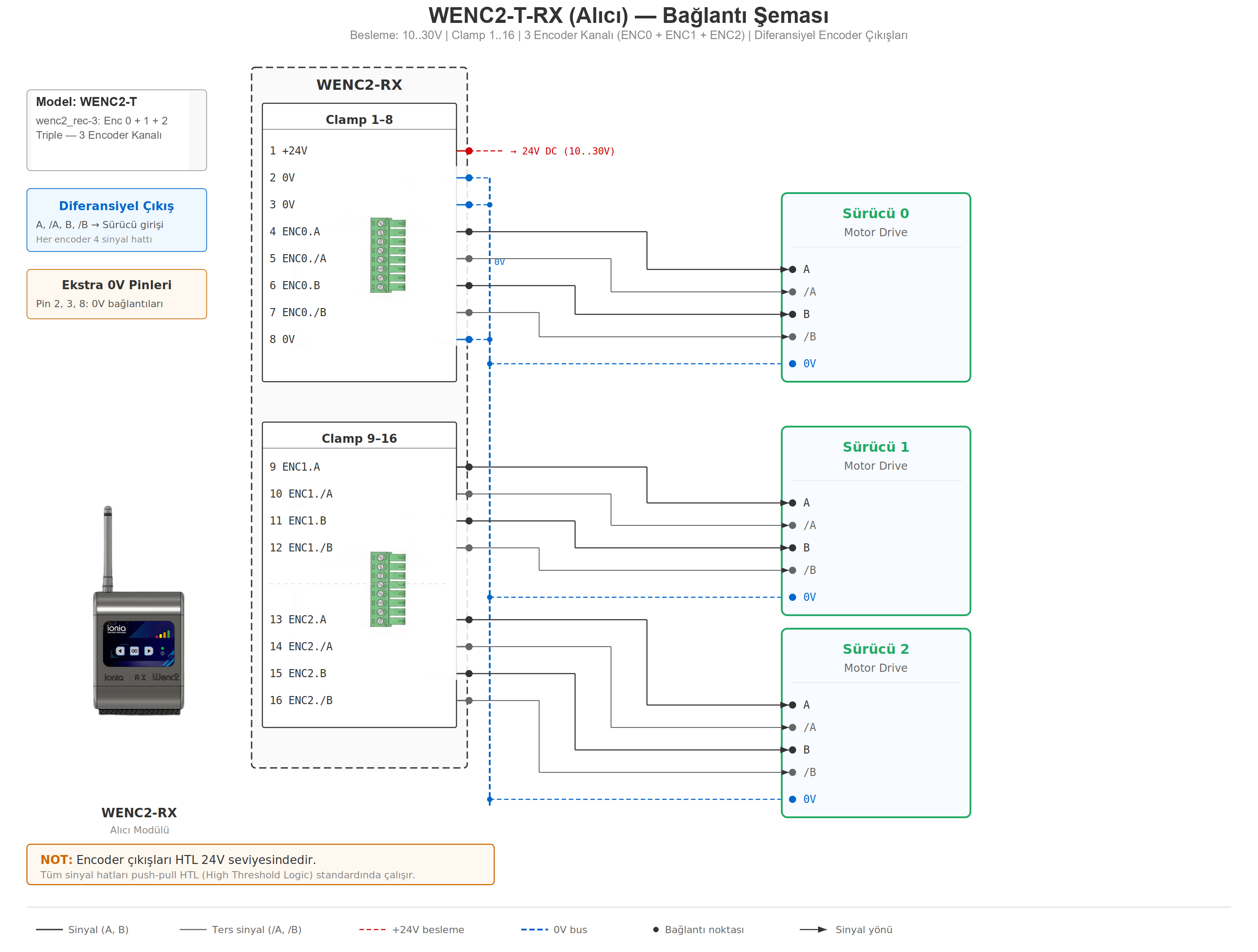
WENC2-T RX
Triple encoder, drive side
Web Interface (Service Mode)
Pair, monitor, diagnose and update from a tablet or phone
Live Monitoring
Live rotation view for each channel; instant RPM, Hz, direction (CW/CCW/Stop) and signal strength with dBm value.
A/B Signal and Cable Diagnostics
A and B levels are shown in colour (green = HIGH, red = LOW). The TX interface checks the cable without pairing: idle / check B / check A / phase / OK.
Pairing and Locate
Scans nearby TX units and creates a persistent pairing. The "Locate" command flashes the device LEDs for ~5 s to show where it is.
Restart Counter
Counts momentary supply interruptions. High TX increase → poor slip-ring contact on the motor side. High RX increase → drive-side supply problem.
Wireless Firmware Update
Signed and encrypted update package; each device is updated over its own WiFi network, no cable needed. Foreign, corrupt or wrong-model packages are rejected.
System Information
TX and RX temperature, firmware version and date, MAC addresses, last reset reason; a black-box log of the last 64 events can be downloaded. Interface language: Turkish / English.
Operating Modes and Single Button
Normal Operation
Paired devices connect automatically at power-up and encoder data is transmitted in real time. The WiFi access point is off; the LEDs show signal strength.
Service Mode
For pairing, monitoring, settings and updates. The device opens a WiFi access point. In service mode the RX output updates at ≈ 100 ms intervals and is not suitable for closed-loop operation.
LED Signal Bar
4 LEDs show signal strength: 4 LEDs > −57 dBm, 3 LEDs > −67 dBm, 2 LEDs > −75 dBm, 1 LED > −85 dBm. Both TX and RX show the bar.
Single-Button Operation
| State | Action | Result |
|---|---|---|
| Normal operation | Hold 5 s | Switches to service mode; the paired device is also called into service mode. A short press is ignored (no accidental switching). |
| Service mode | Short press | Locate: the paired device's LEDs flash for ~5 s. |
| Service mode | Double short press | 60 s pairing window. When pressed twice on both devices, TX and RX pair automatically; no web interface needed. |
| Service mode | Hold 3 s | Leaves service mode and returns to normal operation. |
| At power-up | Hold | Starts in service mode. |
| At power-up | Hold 10 s | Factory reset (serial number and model are kept). |
Secure Update
Automatic Rollback on Failure
After an update, the new firmware must validate itself within 60 seconds. If it does not, the device automatically returns to the previous working firmware. If an upload is interrupted, the device starts with the old firmware.
Signed Package and Version Protection
Only a signed and encrypted package for the correct model is accepted. Anti-rollback protection prevents older firmware from being installed.
Troubleshooting
Quick diagnostic guide
| Symptom | Possible Cause | Solution |
|---|---|---|
| LEDs not lit | No power or no signal | Check the supply (15–30 V). In normal mode the LEDs stay off when there is no signal. |
| Pairing fails | Devices not in service mode | Put both devices into service mode; for button pairing, double-press on both devices. |
| Web interface doesn't open | Wrong WiFi or mobile data | Connect to the network starting with WENC_ and turn off mobile data; use http://192.168.10.1 (not HTTPS). |
| Encoder turning, no count at the drive | Cable fault or RX in service mode | Use the A/B diagnostics in the web interface. If the RX is in service mode, return it to normal operation. |
| Direction inverted at the drive | A/B order reversed | Invert it in the drive parameters; or swap A and /A on a 4-wire connection, or ENC.A and ENC.B on the TX for a 2-wire connection. |
| All indicators red | No encoder supply | The cable may be broken; on a 2-wire connection check the /A, /B → GND bridge on the TX. |
| Indicators don't change | Broken signal wire | Check the corresponding A or B line. |
| Position oscillates ±1 | Wrong wiring | Check the A/B/~A/~B connection order. |
| Frequent restarts | Slip-ring contact or supply problem | Compare the counters: TX increase → slip-ring maintenance; RX increase → drive-side supply. |
| Not working after an update | Faulty firmware | The device returns to the previous version automatically within 60 s. |
Order Information
Order Codes
| Order Code | Encoder Channels | Contents |
|---|---|---|
| WENC2-MONO (S) | 1 encoder | 1 × TX + 1 × RX paired kit |
| WENC2-DUO (D) | 2 encoders | 1 × TX + 1 × RX paired kit |
| WENC2-TRI (T) | 3 encoders | 1 × TX + 1 × RX paired kit |
Standard Package Contents
- 1 × TX transmitter module
- 1 × RX receiver module
- 2 × external 5 GHz antennas (1.1 dBi)
- 4 × 8-pin 3.81 mm pluggable screw terminal sockets
- Cardboard packaging